Active Aerodynamics Controller

Race cars enjoy the benefits of aerodynamics to further shorten lap times and increase lateral G’s. Many aero systems are fixed, which inhibits top speed due to drag. Modern Formula 1 cars have a drag reduction system, or DRS, that can manually be triggered for straights, reducing the drag and allowing for faster speed. Once the car approaches the corner the driver can disable the DRS thus enabling full down force for maximum corner grip and thus maximum corner speed. We envision a product that takes this concept a step further to both automate this process to allow the driver to focus more on racing, and increase the responsiveness and precision that an automated system can deliver.
The System:
The system is logically split into three layers:
The Data Acquisition Layer:
This layer is responsible for reading the raw data from an IMU or Inertial Measurement Unit and applies a digital filter to the signal to reduce unwanted noise and anomalies.
The Node Control Layer:
This layer is responsible for receiving commands from the main control layer and enforcing those commands on physical control surfaces arranged around the car. It determines the position of the control surfaces by means of limit switches mounted on the car.
The Main Control Layer:
This layer is responsible for interpreting the data from the acquisition layer and orchestrating the control of the nodes in order to make the cars aero package, that is all control surfaces working together, function to the benefit of the driver.
The Hardware:
From the outset, we chose to stick with components that were sufficient enough to do the job, but not excessively expensive such that the end result would never be a viable product.
With this in mind we chose the following components:
Node Board:
Teensy 3.2 Arduino-compatible 32bit ARM Cortex M4 based microcontroller
Texas Instruments SN65HVD230 3.3V CAN Transceiver
Optically isolated digital inputs for control surface feedback
On board power regulation for protection against voltage fluctuations

Main Board:
Teensy 3.5 Arduino-compatible 32bit ARM Cortex M4 based microcontroller
Texas Instruments SN65HVD230 3.3V CAN Transceiver
Optically isolated digital inputs for human control feedback
On board power regulation for protection against voltage fluctuations
MPU9250 9-axis IMU

CAN Application Layer Protocol
Rather than using the 11 bit CAN identifier to address each node individually, we decided a protocol is necessary to spread all of the functionality across the address space to facilitate ease of use and clarity of messages on the bus.
We achieved this by segmenting the 11 bit address space into two sections, the upper 5 bits of the address are reserved for “opcodes” so to speak, and the lower 6 bits are reserved for the address which an opcode is to act upon.
By doing this we can easily apply bit shifting to the message IDs and quickly figure out what is trying to be accomplished in the program.
The opcodes are given by the following table:
PCBs acquired!
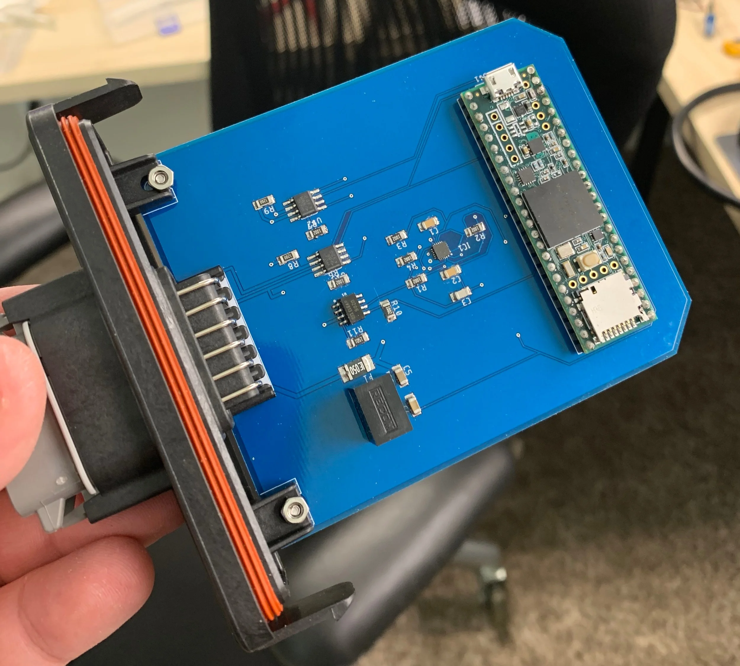
Main Controller Board PCB soldered to automotive Deutsch Connector.
PCBs were ordered and assembled. Using the provided stencils from the PCB house allowed the soldering of tiny packages with ease using a hot air rework tool. We received these boards just in time for Innovation Day 2019 at UTA. For our demo we utilized the “Data Out” feature of Forza Motorsport 7 to output over 70 parameters to a WiFi enabled micro controller that was able to act as a stand in for our main board. The stand in controller was able to utilize our application protocol to control three nodes as a group, based on data received from the video game.
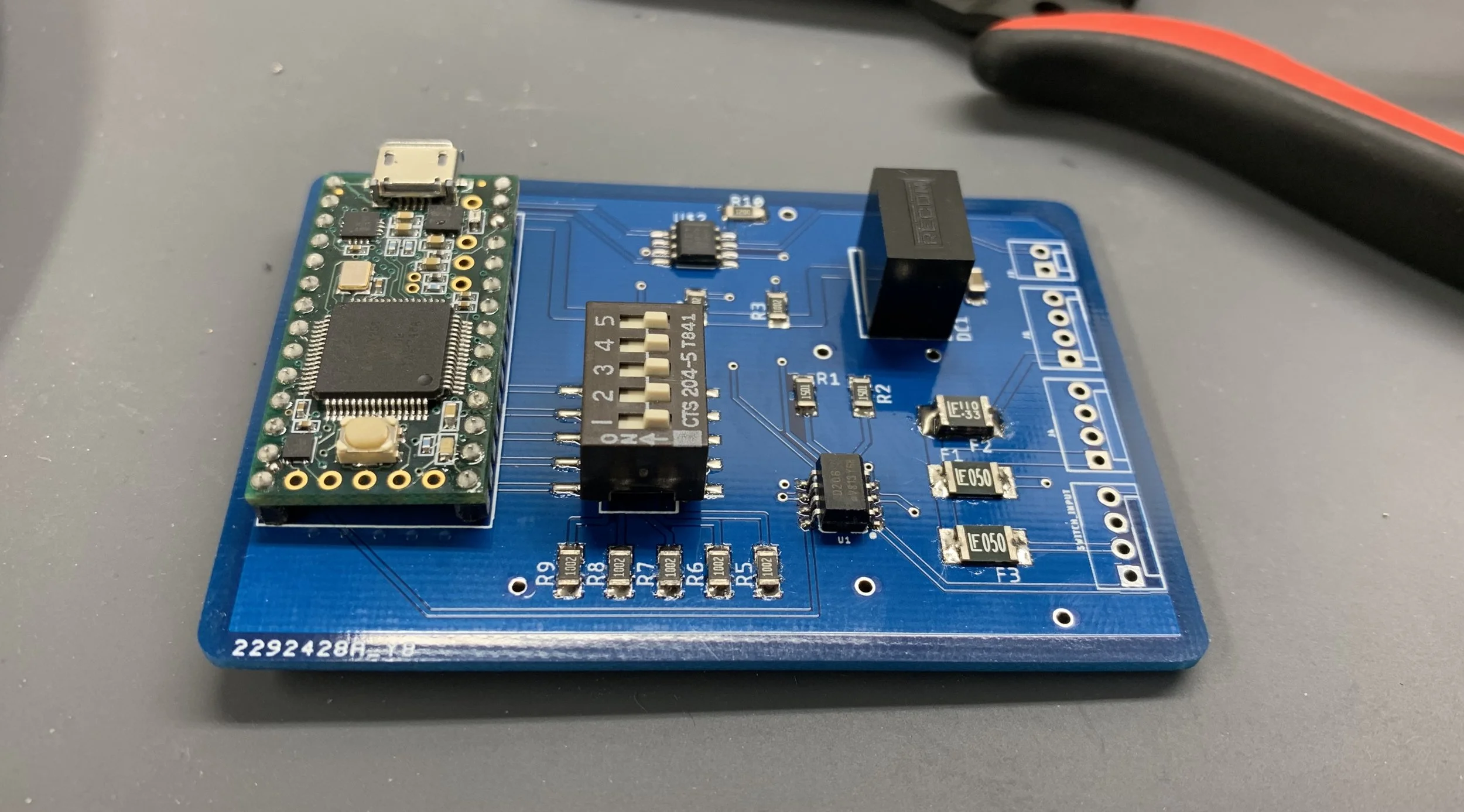
Node board
Innovation Day:
We haven’t had a chance to put the system on a real race car yet, but we were able to use simulation data from a racing simulator game to drive our system, as if it were in a real car.
Using the “Data Out” feature from Forza Motorsport 7 the game sends UDP packets with over 70 parameters at 60 times per second to a WiFi enabled micro controller connected to our system via CANbus. For our demo, we extracted the acceleration vectors from the data and converted them from a cartesian system to polar, applied a 15Hz low pass filter, and used this conditioned data to drive a simple if/then type logic structure for controlling the nodes. Thanks to the simplicity of our application layer protocol, the control of all three nodes could be accomplished with a single message for setting the target of a group, rather than addressing each node individually.
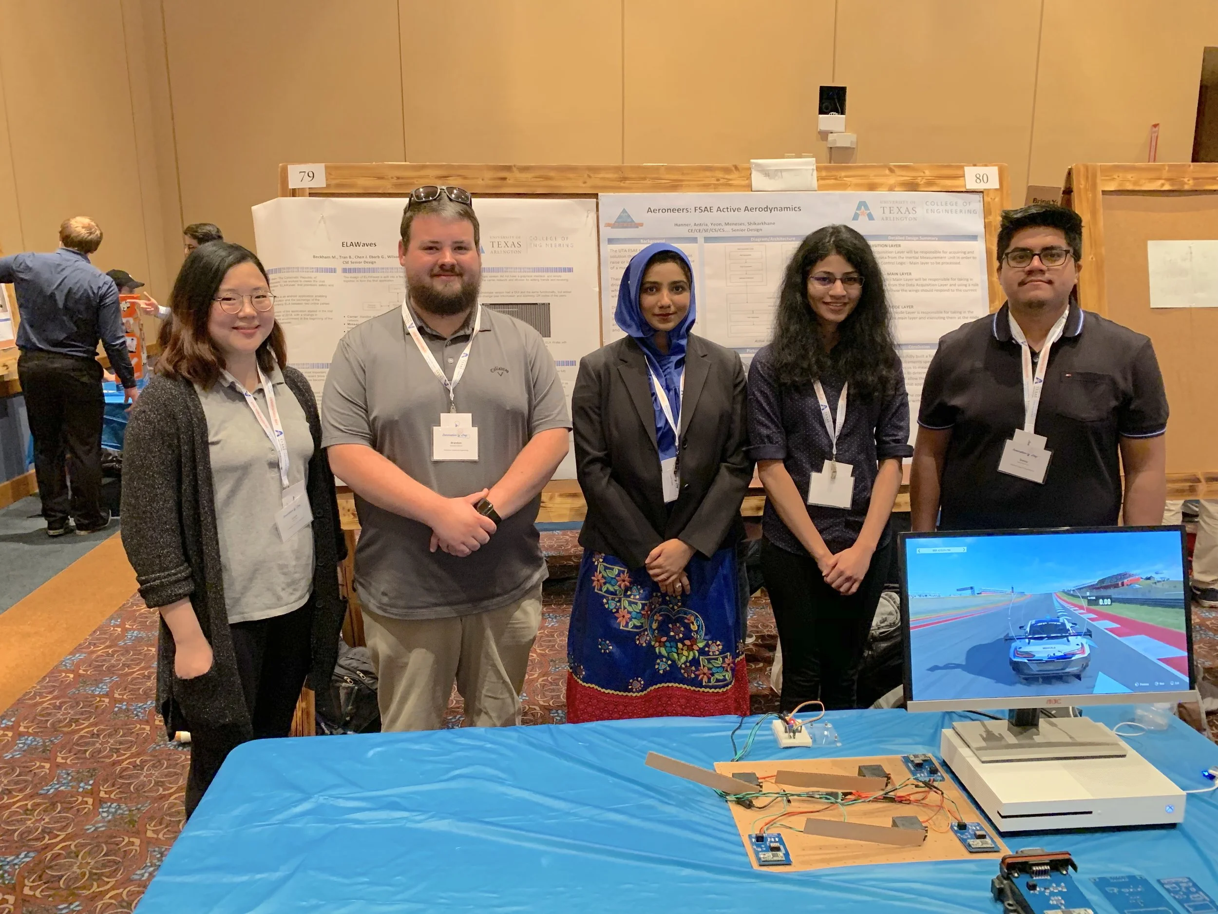
Photo of the team and our demo.
Final Demo:
We finally reached the end of the semester and that means a final demo. We used a similar demo to Innovation day but we turned the polish up.

Using the same WiFi enabled micro controller and the data out feature of Forza Motorsport 7, we turned our attention to the fit and finish of the project. We 3D printed scale wings to attach to our servos, as well as laser cutting an acrylic piece to put every thing on.
Here is the end result:


